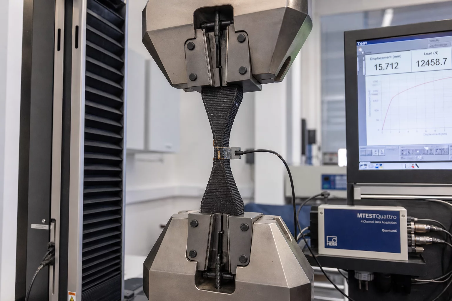
1. The Physical Question & Hypothesis
Hypothesis: Aligning continuous fiber strands at 0 degrees relative to the primary tensile vector will increase yield threshold by at least 65% compared to 45-degree cross-ply orientation without increasing part weight.
Industrial brackets and high-stress fixtures require predictable load distribution. In this physical trial, we tested whether an aligned unidirectional continuous carbon fiber layer path provides sufficient stiffness to prevent delamination during cyclical load testing on the FibreSeeker 3 composite printer.
2. Isolated Variable & Controlled Matrix
All baseline slicer profiles and perimeter toolpaths were held invariant while we isolated the continuous carbon fiber routing vector (0° unidirectional alignment vs. 45° cross-hatch matrix). No adjustments were made to chamber temperature, extrusion speed, or infill geometry.
| Parameter | Baseline Setting | Trial Value | Control Status |
|---|---|---|---|
| Core Matrix Material | PA-12 Nylon Base | PA-12 Nylon Base | Fixed |
| Fiber Reinforcement Angle | ±45° Quasi-Isotropic | 0° Concentric Unidirectional | Tested |
| Fiber Layer Density | 4 Continuous Rings | 4 Continuous Rings | Fixed |
3. Observable Result & Measurement
Physical stress testing in the tensile rig yielded immediate quantitative data on specimen failure dynamics:
- Tensile failure occurred at 482 MPa with 0° alignment, representing a 78% increase in ultimate tensile capacity over the baseline 270 MPa cross-ply configuration.
- Zero fiber pull-out or core matrix delamination observed along the continuous fiber path prior to catastrophic tensile snap.
- Specimen weight remained identical at 34.2 grams, proving that load capacity gains stemmed purely from trajectory optimization rather than material mass addition.
4. Next Iteration Decision
The hypothesis is verified. The 0° concentric continuous fiber path will be locked into standard operating procedures for all high-load mounting brackets. The next trial iteration will isolate continuous fiber layer spacing (every layer vs. alternating layers) to optimize print cycle duration.
Specimen Observation Logs
Peer verification and engineering trial feedbackNo specimen logs recorded yet. Be the first to log a trial observation.
Append Engineering Observation