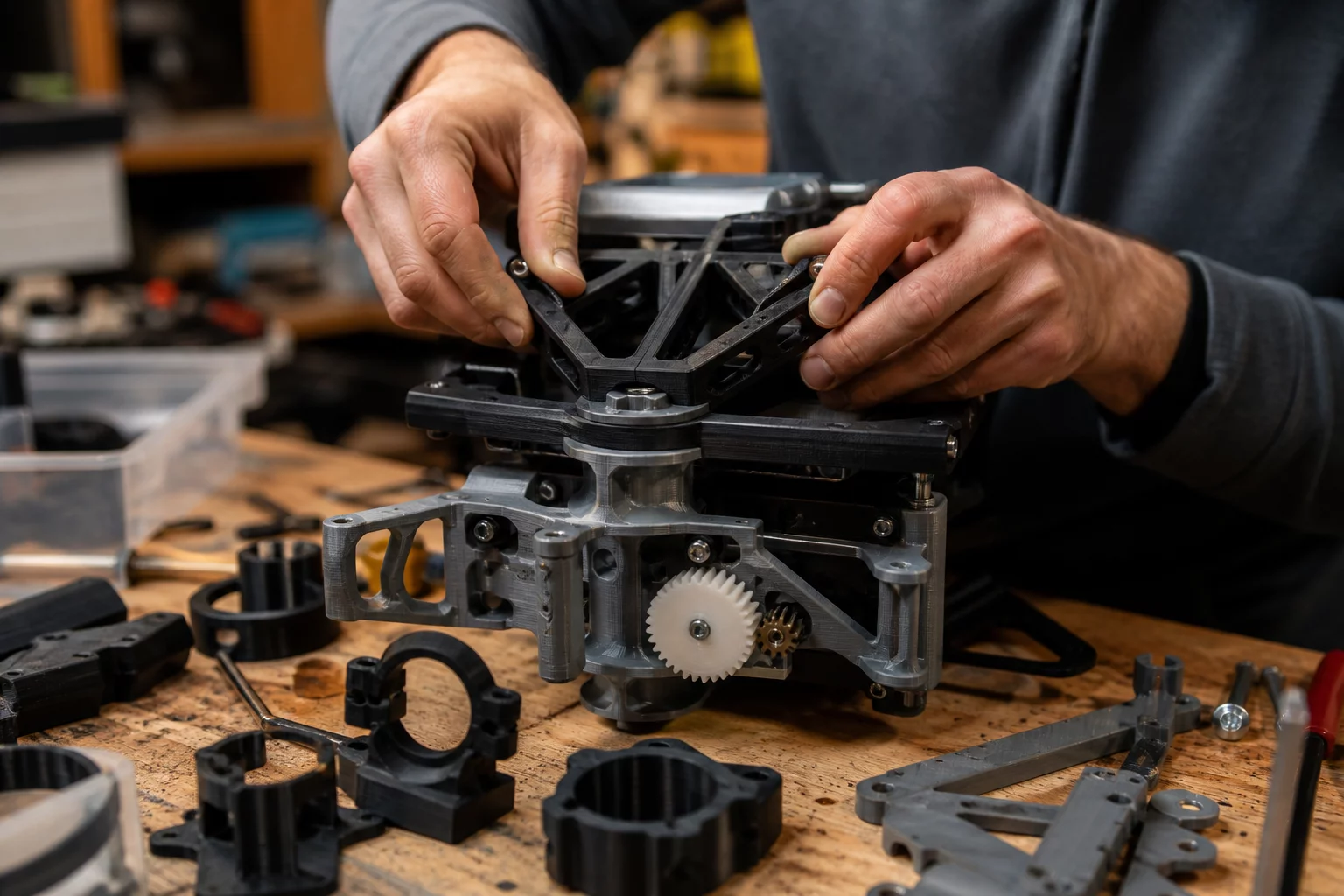
Methodology Overview
Checking the interaction of assembled components.
Every multi-part physical prototype compounds dimensional discrepancies across mating faces, fasteners, and pivot pins. When teams print complete assemblies without isolated joint trials, identifying which specific interface causes mechanical binding becomes nearly impossible. By isolating critical sub-assemblies into compact verification specimens, product designers evaluate mechanical clearances, sliding resistance, and retention force under real operating conditions.
The Assembly Trial ledger forces teams to answer a single kinematic question prior to production slicing. It records measured interface clearances against nominal CAD models, tracks anisotropic shrinkage across distinct print orientations, and ensures that fastening elements seat without inducing stress fractures in adjacent plastic housings.
Interactive Verification Protocol
Stage 1: Define Interface Boundaries
Extract only the mating interface geometry from CAD rather than the entire enclosure assembly.
- Crop structural bodies to within 10 mm of the primary mating joint.
- Record nominal CAD clearance for male and female components.
- Define single success criterion (e.g. zero-wobble smooth slide under gravity).
Stage 2: Orientation and Slicing Control
Align build plate orientations to mirror production layer direction and prevent misleading seam placement.
- Align seam positions away from internal sliding surfaces in PrusaSlicer 2.9.6.
- Keep extrusion width and external perimeter speed identical across parts.
- Print both components on the same build sheet to share thermal exposure.
Stage 3: Physical Assembly & Evaluation
Assemble components in raw as-printed state without secondary filing or scraping, logging exact friction feel.
- Test insertion resistance by hand and check for seam collision.
- Measure gap consistency across all 4 quadrants using feeler gauges.
- Record pass/fail decision in workbook before modifying CAD offsets.
Assembly Ledger Parameter Matrix
| Verification Field | Target Tolerance Band | Assembly Observation Target |
|---|---|---|
| SLIDE-FIT-RADIAL | 0.15 mm - 0.22 mm | Frictionless linear travel without perceptible lateral tilt |
| PRESS-FIT-INTERFERENCE | -0.04 mm - 0.00 mm | Permanent dowel pin retention without housing delamination |
| ROTATIONAL-JOURNAL | 0.20 mm - 0.30 mm | Continuous 360-degree rotation with zero seam catching |
| FASTENER-POCKET-CLEAR | +0.30 mm diametral | M3/M4 hex nut drop-in seating without heat iron requirement |
Request This Workbook Template
Submit this engineering desk dispatch to receive the formatted Assembly Trial PDF workbook, PrusaSlicer template presets, and test specimen CAD files.
Engineering Observation Logs
Verified community test runs and physical specimen notesSubmit Verified Observation
Share recorded physical test findings, dimensional variances, or printer configuration insights.
No observations recorded yet. Be the first to log a verified physical test run for this assembly trial.