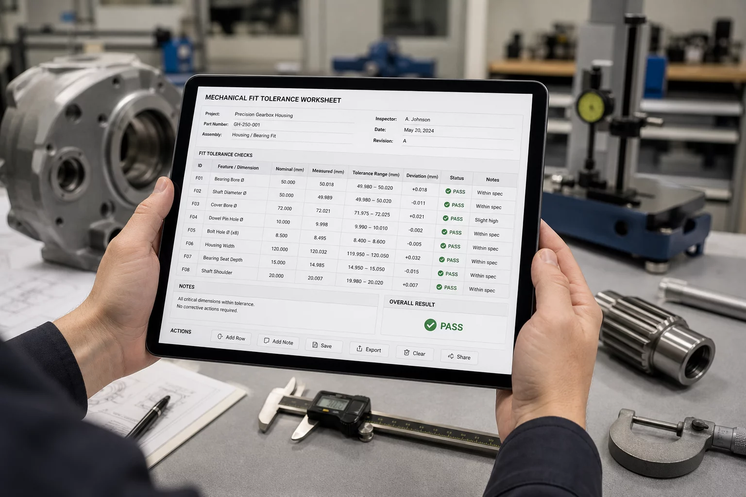
Summary & Trial Objective
Interference and clearance fits often deviate due to thermal contraction, perimeter overlap, or slicer hole calculation behaviors. This guide outlines how to isolate mating features into compact test coupons, state a singular dimensional question, record real caliper feedback, and make objective go/no-go decisions.
1. Problem Definition and Hypothesis
Prototyping teams waste excessive filament and build time by re-running entire multi-hour enclosures whenever an internal mounting boss or sliding latch binds. A Fit Trial isolates the exact contact interface into a fast 20-minute coupon print. The target is never the entire part body; it is strictly the relationship between mating surface walls.
Before sending G-code to the machine, formulate an explicit hypothesis in your physical or digital ledger. State the intended fit class (free-running, sliding, push fit, or permanent press fit) alongside the single slicer parameter being altered. In PrusaSlicer 2.9.6, compensation settings like X-Y Hole Compensation or Slice Gap Clearance should be adjusted systematically rather than modifying core CAD geometry prematurely.
| Trial Variable | Baseline Parameter | Adjusted Variant | Expected Observable |
|---|---|---|---|
| X-Y Hole Compensation | 0.00 mm |
+0.12 mm |
608 Bearing seats flush with steady hand pressure without cracking the perimeter wall. |
| Perimeter Extrusion Width | 0.45 mm |
0.40 mm |
Snap-fit cantilever arm deflects 1.2 mm without permanent plastic deformation or seam binding. |
2. Step-by-Step Observation Protocol
Follow a strict observation routine once the print bed cools to room temperature. Premature removal while parts remain warm introduces warping that invalidates tolerance measurements.
- Thermal Equilibrium Verification: Allow both male and female test specimens to rest at ambient shop temperature for 15 minutes before measuring with digital vernier calipers across multiple perpendicular axes.
- Engagement Force Assessment: Slide or snap the mating parts together by hand without lubricant. Note the exact location of friction rings, seam interference, or corner bulging.
- Disassembly & Wear Check: Separate the components five consecutive times to evaluate whether layer boundaries delaminate or retain friction under cyclic engagement.
Golden Principle
One print. One question. One observable result. Do not alter secondary parameters until the primary feature is validated against physical thresholds.
3. Evaluation Criteria and Thresholds
Document the result directly in your worksheet ledger with a definitive status: Accept, Iterate, or Reject. If the bore requires filing or reaming to seat, the trial is marked incomplete and a +0.05 mm step is applied to the next coupon run. When both engagement force and dimensional clearance match engineering targets, lock that parameter set and proceed to full assembly production.
Field Observations & Logs
No observations logged yet. Be the first to publish a trial specimen entry.
Submit Field Log Entry