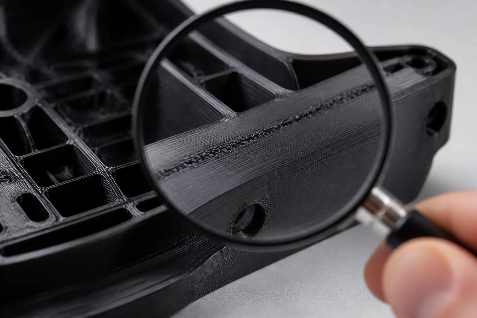
Summary & Trial Objective
Prototypes do not require perfection to yield definitive answers. A test print has provided enough evidence the moment it confirms or refutes your single target hypothesis with repeatable, measurable physical indicators. Continuing to print beyond this threshold drains workshop hours and filament without reducing project risk.
1. Problem Definition and Hypothesis
Every exploratory trial begins with a clear operational hypothesis, such as determining whether a 0.2 mm clearance allows a sliding rail to glide freely without lateral play. When the printer finishes, technicians often fall into the trap of analyzing peripheral details like surface sheen or top layer patterns that have zero bearing on the mechanical question. The primary objective is to inspect solely the targeted feature against predefined go/no-go limits.
Conclusive evidence in rapid prototyping comes down to direct physical verification rather than cosmetic evaluation. Caliper readings within the target envelope, clean mechanical engagement without binding, and absence of structural delamination provide all the proof necessary to approve the CAD geometry. Once these measurable benchmarks are satisfied, the current iteration is validated and ready for full assembly integration.
| Trial Variable | Baseline Parameter | Adjusted Variant | Expected Observable |
|---|---|---|---|
| Interference Fit Clearance | 0.15 mm offset |
0.25 mm offset |
Smooth sliding action with <0.05 mm play |
| Wall Perimeter Count | 2 perimeters (0.8mm) |
4 perimeters (1.6mm) |
Zero flex under 15 N perpendicular load |
2. Step-by-Step Observation Protocol
Follow a disciplined inspection sequence immediately after removing the test specimen from the build plate. Allow the part to cool to ambient workshop temperature (21°C) to prevent thermal distortion from skewing dimensional measurements.
- Measure Primary Critical Dimensions: Use calibrated digital calipers or micrometers to record three separate points along the functional engagement face.
- Perform Physical Mating Verification: Test the physical interaction with the mating hardware or companion part under real assembly force conditions.
- Record Binary Pass/Fail Decision: Log the result into the trial worksheet and immediately transition to next-stage CAD integration if thresholds are met.
Golden Principle
One print. One question. One observable result. Do not alter secondary parameters until the primary feature is validated against physical thresholds.
3. Evaluation Criteria and Thresholds
Set quantitative acceptance boundaries prior to slicing. If the design requirement specifies a snap force between 8 N and 12 N, any specimen operating inside that window represents sufficient proof. Spending time tuning retraction or ironing to make the test piece look flawless adds zero informational value to your mechanical decision.
Field Observations & Logs
The systematic worksheet approach completely eliminated guesswork on our snap-fit latch trial. Documenting one variable per run prevented us from wasting an entire spool on failed dimension calibrations.
Submit Field Log Entry